English

Project Background
A leading fluid dynamics technology enterprise designed a special equipment booster pump impeller. This impeller features specific material composition, precise structural dimensions, and stringent performance requirements, necessitating a detailed processing plan to ensure product quality.
This equipment serves as a high-pressure booster pump for reverse osmosis (RO) systems. It must withstand high pressure and resist long-term corrosion from chloride ions in various water qualities, such as seawater.
Particularly critical is the nickel-based high-temperature alloy cladding applied to the blade edges. This material is indispensable in extreme environments, delivering long-term stability under high temperatures (typically exceeding 600°C), high pressure, severe mechanical stress, and harsh chemical corrosion. Its core value lies in maintaining strength, creep resistance, fatigue resistance, and corrosion resistance under these demanding conditions.
Key Parameters of the Impeller
(1) Material Properties
Main Material: 316 Stainless Steel,Edge Reinforcement Material: 1.5mm thick nickel-based high-temperature alloy welded to the blade edges via cladding process.
(2) Structural Dimensions
Number of Blades: 5, Impeller Diameter: 318mm, Impeller Height: 108mm.
(3) Performance Requirements
Dynamic Balance Grade: G1.0, Dynamic Balance Test Speed: 750 rpm.
Geometric Tolerance Requirements: - Symmetry: 0.01 mm, - Radial Runout: 0.01 mm, - Cylindricity: 0.006 mm
Surface Roughness: Ra 0.6.
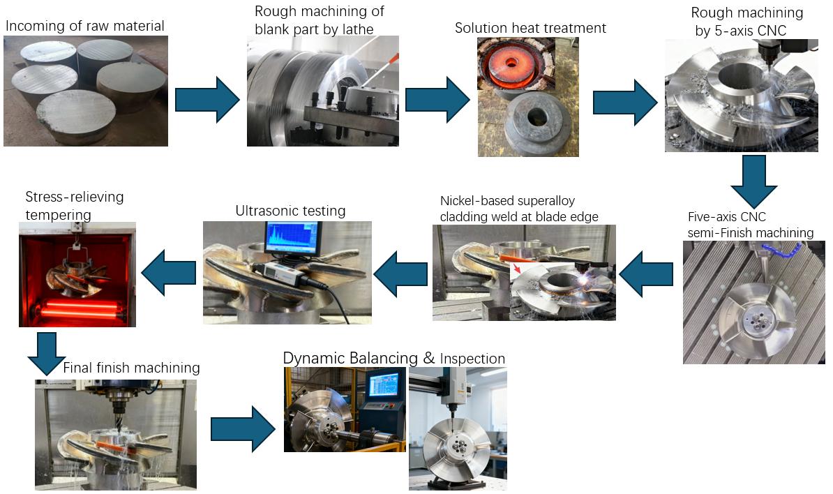
Processing Steps and Processing Time Assessment- The processing diagram is shown at the bottom of the page
Items | Processing stage | Specific content | Working hours |
1 | Rough machining of the blank workpiece on lathe | Perform preliminary lathe machining on the raw materials. | 8 |
2 | Solution heat treatment | Solution heat treatment of the material allows elements such as carbon, chromium, and nickel to redissolve within the austenitic structure, preventing the precipitation of intergranular carbides (and thus avoiding intergranular corrosion). This improves the material's plasticity, toughness, and corrosion resistance, preparing the microstructure for subsequent high-precision machining and welding. Key parameters: Heating temperature: 1040°C - 1100°C. Holding time: 3 hours. | 15 |
3 | Five-axis CNC rough machining | Five-axis CNC roughing with high feed rates | 10 |
4 | Five-axis CNC semi-Finish machining | From semi-finishing to leaving a 1mm allowance to the final finishing process | 10 |
5 | Nickel-based superalloy cladding | Perform nickel-based high-temperature alloy cladding overlay welding on the specified area along the blade edge, with a thickness of 1.5 mm. | 15 |
6 | Ultrasonic testing is performed after the cladding process. | After the cladding weld process, ultrasonic testing is performed. The testing focuses on: Cracks: Cold or hot cracks caused by welding thermal stress. Lack of fusion: Poor bonding between the weld overlay and the 316 stainless steel substrate. Porosity and slag inclusions: Caused by improper protection or incomplete cleaning during the welding process. | 15 |
7 | Stress-relieving tempering | To address the impact of nickel-based superalloy cladding welding on workpieces, tempering treatment is performed on the welded area and the entire component. The main purpose is to significantly reduce or eliminate the high residual stress generated during the welding process. Key parameters: Heating temperature: 550°C - 650°C. This temperature is below the precipitation-sensitive temperature range of chromium carbide, effectively relieving stress without significantly reducing the material's strength and corrosion resistance. Holding time: Typically 3 hours to ensure full stress release. Cooling method: Furnace cooling or slow furnace cooling is used to avoid introducing new thermal stress. | 13 |
8 | Final finishing | Using special alloy cutters, precision machining is performed with minimal feed rate, and the cutting tools are changed every half hour. | 15 |
9 | Inspection and Acceptance | After processing, dynamic balancing tests and full-dimensional measurements are performed, and final acceptance is conducted according to relevant standards. | 15 |
Total working hours: | 116 |
Quality Control and Acceptance Criteria
(1) Process Inspection
Non-destructive Testing: After the cladding process is completed, inspect the workpiece interior for Gas porosity, cracks, or other defects.
Cutting tools Management: Due to the hard surface of nickel-based high-temperature alloys, special alloy tools are used during finishing operations. Cutting tools must be replaced every half hour to ensure machining accuracy.
(2) Final Acceptance
Dynamic Balancing Test: Dynamic balancing measurement results must achieve G1.0 grade.
Dimensional Measurement: full-dimensional measurement report and 3D coordinate measurement results file.
Surface Quality: Test results certifying surface roughness Ra0.6.
Certification Materials: The following documents must be provided as acceptance basis:
Material Composition Certificate
Solution treatment and tempering heat treatment process certificates
Workpiece non-destructive testing certificate
Nickel-based high-temperature alloy remelting process specification.
Summary
This report clearly defines the material properties, key parameters, machining process steps, and quality control and acceptance standards for impellers of special equipment medium-pressure pumps. Each phase must be strictly executed according to the established plan to ensure the machining quality of impellers meets the company's stringent requirements. During subsequent production, close attention should be paid to the implementation of each process, with timely adjustments and optimizations to ensure the smooth progress of the project.
Processing flow diagram for reference