English
Deciphering the mechanical capabilities of modern manufacturing centers requires a deep dive into how a machine maneuvers raw material relative to a cutting edge. In precision machining, the complexity of a part is dictated entirely by the configuration of its moving parts. Choosing between various CNC axis types is not merely a question of adding hardware; it is a strategic calculation that balances spatial dexterity against rigidity, cycle efficiency, and tooling economics.
For international procurement managers, industrial engineers, and factory owners, mastering this kinematic hierarchy is essential. It allows you to align your component blueprints with the most cost-effective machining method, ensuring tight geometric tolerances while cutting out unnecessary lead times in the production pipeline.
1. What Do We Mean by "Axis"? Understanding the Basics
The term "axis" in CNC manufacturing refers to an independent, software-controlled vector of movement along which a cutting tool or workpiece travels relative to the machine chassis. This directional framework forms the backbone of Computer Numerical Control (CNC) positioning. The foundational movement structure relies on the Cartesian coordinate system, which maps out physical space across three perpendicular lines intersecting at a single origin point.
In a standard machine setup, these directions dictate how the computer reads G-code commands to coordinate the mechanical ball screws, linear guides, and servomotors. By precisely executing multi-axis coordinate movements simultaneously, a CNC system transforms digital CAD files into tangible, high-precision industrial components with sub-micron repeatability.
2. Function of Linear Axes and Rotary Axes
Linear axes and rotary axes function as the dual mechanical components of CNC movement, where linear paths dictate straight-line travel across flat coordinates and rotary paths introduce angular positioning to rotate parts or tools. To fully understand industrial component manufacturing, you must break down how these two distinct systems interact within a modern machining envelope:
Linear Axes (X, Y, Z): These represent the classic movements along three straight, mutually perpendicular lines. The X-axis controls horizontal left-to-right movement; the Y-axis governs lateral front-to-back depth; and the Z-axis directs vertical up-and-down movement, which typically aligns with the centerline of the machine spindle.
Rotary Axes (A, B, C): These introduce rotational degrees of freedom by pivoting around the core linear baselines. Following standard engineering conventions, the A-axis rotates specifically around the X-axis, the B-axis rotates around the Y-axis, and the C-axis rotates around the Z-axis.
By combining linear straight-line cutting paths with rotary angular adjustments, advanced manufacturing centers can position cutting tools at optimal angles, which eliminates part deflection and allows machining inside complex undercuts according to ISO 841 standards.
3. Types of CNC Machine Axis: 3-Axis, 4-Axis and 5-Axis
The main structural variations in CNC axis types are defined by the total number of operational coordinates a machine can control at once, starting with standard 3-axis setups and extending to multi-axis 4-axis and simultaneous 5-axis systems. The architectural jump between these machine levels alters how a component must be set up, fixtured, and processed on the factory floor:
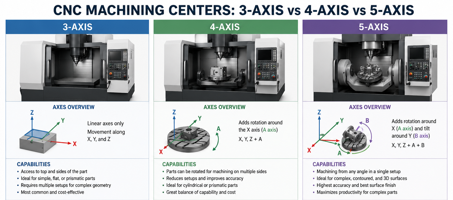
3 Axis CNC Machining Center: This standard configuration utilizes the X, Y, and Z linear directions simultaneously. It is highly effective for processing flat plates and simple mechanical brackets.
4 Axis CNC Machining Center: A 4-axis system adds a single rotary axis (A or B), allowing the workpiece to rotate automatically. It is ideal for engraving cylindrical parts and milling features onto multiple faces without manual intervention.
5 Axis CNC Machining Center: Using all three linear movements alongside two rotational movements at the same time, this setup enables the manufacture of complex geometries like contoured surfaces in a single setup.
To explore how these multi-axis capabilities can be leveraged to streamline your outsourced production runs, browse our complete custom processing profiles on our the 5-Axis CNC Machining Page.
4. Advantages of Different Types of CNC Axis: A Comparative Guide
The relative advantages of different CNC axis configurations lie in balancing upfront equipment costs against total production efficiency, with lower-axis systems offering cost savings for simple geometries and higher-axis systems delivering faster cycles for complex parts. When calculating the total cost of a manufacturing run, reviewing the performance metrics below can help you select the most efficient setup.
| Performance Metric | 3-Axis Milling Systems | 4-Axis Rotary Systems | Simultaneous 5-Axis Centers |
|---|---|---|---|
| Number of Setups Required | High (3 to 5 separate setups) | Moderate (2 to 3 setups) | Minimal (1 to 2 setups total) |
| Positional Tolerances | +/- 0.025 mm | +/- 0.015 mm | +/- 0.005 mm or tighter |
| Geometric Capability | Simple prisms and plates | Cylindrical and multi-sided | Complex undercuts and airfoils |
| Average Setup Reduction | Baseline (0 percent) | 20 to 35 percent | Up to 75 percent reduction |
| Tool Longevity | Low (Requires long extensions) | Moderate | Highest (Uses short, rigid tools) |
5. Why Use 5-Axis CNC Machine for Complex Precision Parts?
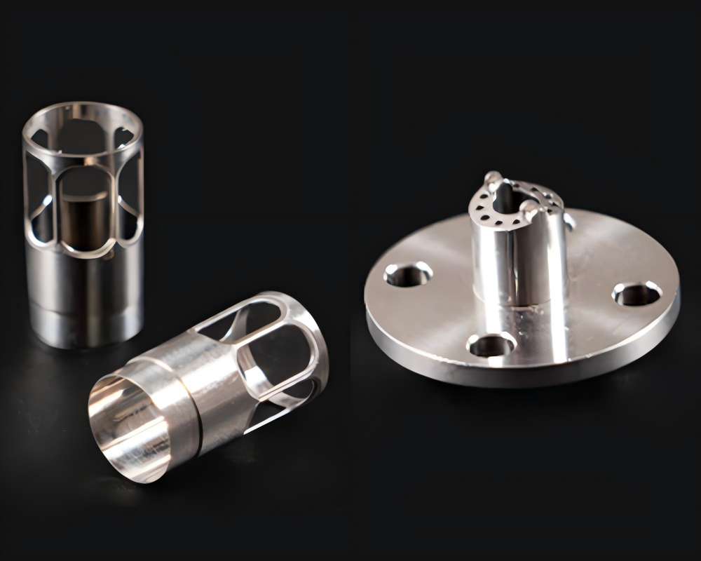
Industrial facilities use 5-axis CNC machines for complex precision parts because the multi-axis movement allows workshops to finish intricate designs in a single setup, which maintains tight tolerances and eliminates manual repositioning errors. In high-stakes fields like aerospace and medical manufacturing, even minor positioning variations can compromise part integrity.
By moving five axes simultaneously, the machine can orient the cutting tool to maintain a constant chip load. This prevents tool dragging and results in ultra-smooth surface finishes (Ra 0.4 microns or lower), matching the standards published by the NIST Manufacturing Frameworks.
6. 3 Types of 5-axis CNC Machine and Their Applicable Scenarios
The distinct types of 5 axis CNC machine setups are categorized by how their rotational axes are mechanically split between the spindle head and the work table to balance part weight against overall geometric agility. Choosing the right mechanical configuration is essential for keeping cuts rigid and accurate across different part weights:
Trunnion Table Configuration (Table-Table Style)
In a trunnion-style machine, both rotational axes are built directly into the moving work table. This layout provides excellent torque and structural stability, making it the ideal choice for heavy material removal on compact, dense parts.
Swivel Head Configuration (Head-Head Style)
A swivel head system places both rotational axes within the articulation of the top spindle housing, while the workpiece remains stationary on a fixed base table. It is the industry standard for processing long, heavy structural parts like aircraft wing spars.
Head-Table Configuration (Hybrid Style)
The hybrid configuration splits the movement by placing one rotational axis in the articulating spindle head and the other on the rotary work table. This balanced arrangement offers a versatile working envelope for mid-sized complex components.
Configuration Performance Comparison Matrix
| Machine Configuration Type | Moving Structural Element | Max Workpiece Weight | Rigidity and Torque | Best Suited Scenarios |
|---|---|---|---|---|
| Trunnion Table Style | Table tilts and rotates | Compact (Under 500 kg) | Exceptional | Automotive blocks, mold cores |
| Swivel Head Style | Spindle head swivels | Heavy (Over 2000 kg) | Moderate | Wing spars, large turbine blades |
| Head-Table Style | Head and Table hybrid | Mid-Weight (500-1500 kg) | Balanced | Medical implants, toolroom parts |
To discover how we deploy these diverse multi-axis layouts to guarantee long-term production reliability for global supply chains, review our complete corporate capabilities in our company profile.
7. How To Get Professional 5-Axis CNC Machining Services?
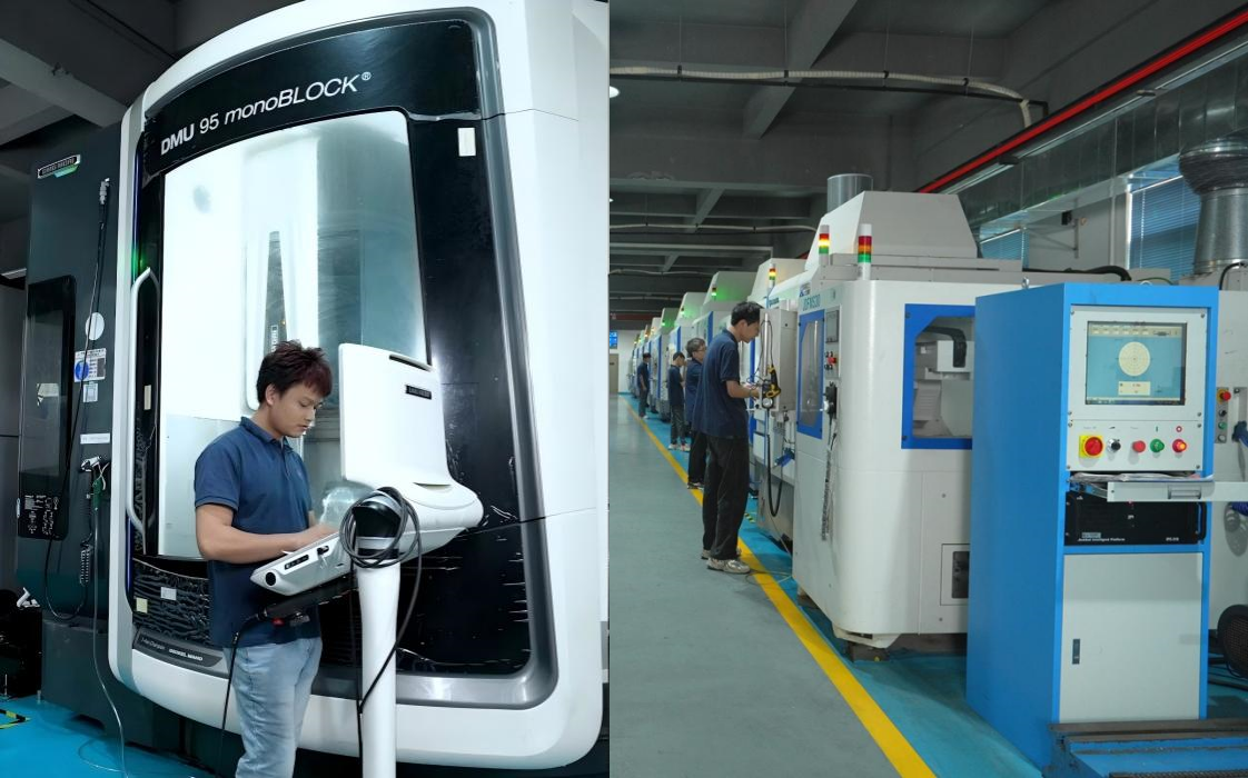
Securing professional 5-axis CNC machining services requires choosing a contract manufacturer that couples modern multi-axis machinery with verified quality control systems and robust CAM programming verification software. At Zhihui Precision, our advanced multi-axis production lines are driven by high-performance Brother, Mazak, and Fanuc controller ecosystems, perfectly integrated with advanced multi-axis CAM software to execute complete digital twin simulations that eliminate toolpath interference and gouging before cutting metal.
A reliable B2B manufacturing partner must offer transparent material traceability, Coordinate Measuring Machine (CMM) dimensional inspection reports, and engineered workholding solutions designed to lower total production costs.
Frequently Asked Questions (FAQ)
1. What is the primary difference between a linear axis and a rotary axis?
A linear axis guides a tool along a straight line (X, Y, or Z), while a rotary axis rotates the tool or workpiece around those linear vectors (A, B, or C).
2. Can a 3-axis CNC machine produce a part with angles on multiple sides?
Yes, but it requires manual stopping and re-fixturing for each face, which increases setup times and introduces potential alignment errors.
3. What is positional 3+2 axis machining?
It means the machine tilts the workpiece into a fixed angular position using two rotary axes, then locks them and performs the actual cutting using only the three linear axes.
4. How do different CNC axis types affect overall tooling costs?
Higher-axis machines allow shorter, more rigid tools to be used, which significantly reduces tool vibration, chatter, and premature breakage.
5. Which 5-axis configuration is best for oversized parts?
The Swivel Head (Head-Head) style is best because the workpiece stays stationary on the floor, eliminating gravitational load errors.
6. How does Zhihui Precision ensure part accuracy?
Zhihui Precision uses advanced laser calibration and dynamic ballbar testing to correct micro-geometric misalignments, backed by comprehensive CMM inspection reports.
Conclusion
Understanding the differences between CNC axis types is essential for selecting the right manufacturing process and managing production costs. While 3-axis systems remain reliable for straightforward components, simultaneous 5-axis machining centers offer the geometric freedom and dimensional fidelity required for modern high-tech industries.
At Zhihui Precision, we operate over 50 advanced multi-axis production lines within our 10,000-square-meter facility, supported by a professional technical team of over 100 experts. We absorb the complexities of multi-axis programming and high-tier calibration, delivering a dependable contract manufacturing foundation for your custom components—from rapid prototyping to large-scale production runs.
Ready to elevate your component precision and optimize your supply chain? Contact our engineering team today on our contact page to request a detailed DFM evaluation and an instant manufacturing quote.