English
Before Starting: What Makes 5-Axis CNC Setup Unique?
The uniqueness of a 5-axis CNC machine setup lies in managing the continuous, dynamic spatial relationship between linear tool positioning and multi-axis part rotation while maintaining a single, unified reference coordinate system. When configuring a standard 3-axis mill, you only need to locate a static workpiece along three straightforward planes: X, Y, and Z. Once your Work Coordinate System (WCS, typically designated as G54) is set via an edge finder or standard probe, the workpiece coordinates remain entirely static throughout the entire machining cycle.Learning how to set up a 5 axis cnc machine requires mastering an entirely different kinematic reality. Because the worktable tilts or the spindle swivels dynamically, the physical location of your part shifts through 3D space every single time an angular axis (A, B or C) moves.To bridge this gap without forcing programmers to manually recalculate thousands of coordinate offsets, modern multi-axis controllers rely on a foundational hardware management process:Dynamic Coordinate Inversion: The CNC controller must continuously track the distance from the physical pivot points of the machine’s tilting tables or swivel heads directly to the tool tip.
Complex Angular Compensation: If a rotary axis tilts by even 0.001°, the controller must execute real-time, micro-linear adjustments along the X, Y and Z axes to keep the cutting flutes exactly where they belong relative to the moving material.
Pre-Setup Preparation: Tools and Safety Checklists
Pre-setup preparation is the strict protocol of inspecting raw stock materials, calibrating precision measuring instruments, and running safety hardware checks to ensure a stable machining environment before executing a program. Before mounting your workholding equipment or loading raw material, you must gather specialized tools and complete a comprehensive safety audit. Operating a high-speed simultaneous multi-axis center with uncalibrated tools or loose enclosures poses severe safety risks.Essential Multi-Axis Setup Toolkit
High-Precision Calibration Sphere: Typically ranging from 12 mm to 25 mm in diameter, featuring a certified sphericity tolerance within ±0.001 mm.
Automated Touch Probes: Radio-frequency or optical infrared spindle-mounted probing systems used to automatically locate part datums and measure tool lengths.
Digital Torque Wrenches: Essential for tightening workholding fasteners to exact footprint specifications, preventing part distortion or clamping failure under heavy rotational forces.
Pre-Flight Operator Safety Checklist
Enclosure Window Inspection: Verify that all poly-carbonate safety windows are completely free of deep scratches or structural cracks.
Axis Way-Cover Clearance: Ensure that all linear axis telescoping covers are clean, lubricated, and free of packed chips that could cause an axis jam.
Spindle Taper Cleanliness: Clean the inner spindle taper with a dedicated wiper tool to eliminate micro-debris. Even a 5 μm particle inside the taper can create noticeable tool runout at the tip.
Step 1: Implementing 5-Axis Workholding and Fixture Strategies
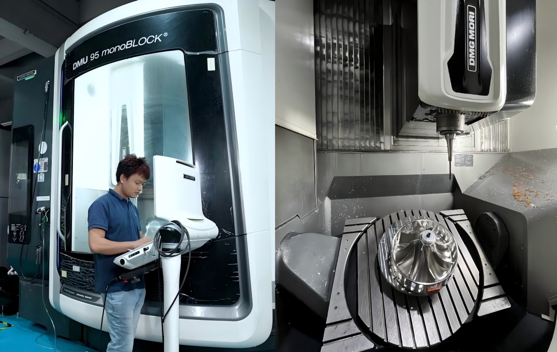
5-axis workholding and fixture strategies involve utilizing specialized clamping hardware to securely anchor a raw workpiece while providing maximum geometric clearance for the cutting tool and spindle housing across all angles of movement. Traditional low-profile milling vises do not work well in a simultaneous 5-axis environment. Because the machine table tilts dynamically, standard wide vises quickly block the spindle's path, causing severe tool holder interference. To prevent this, operators must utilize specialized multi-axis workholding equipment.The Self-Centering Five-Axis Vise
These specialized clamping systems feature elevated jaws that lift the raw material high above the rotary table surface. This height extension provides the spindle housing with ample clearance to tilt and machine the lowest edges of the component without striking the table surface.Dovetail Clamping Systems
For heavy-duty roughing operations, a dovetail fixture is highly effective. The operator pre-machines a small, precise 60° dovetail slot into the bottom edge of the raw stock. The fixture locks into this tiny matching groove, securing the block with massive gripping force while requiring less than 3 mm of material interface. This unlocks maximum cutting access to five full faces of the component.Step 2: Calibrating Rotary Axes and Machine Kinematics (COR)
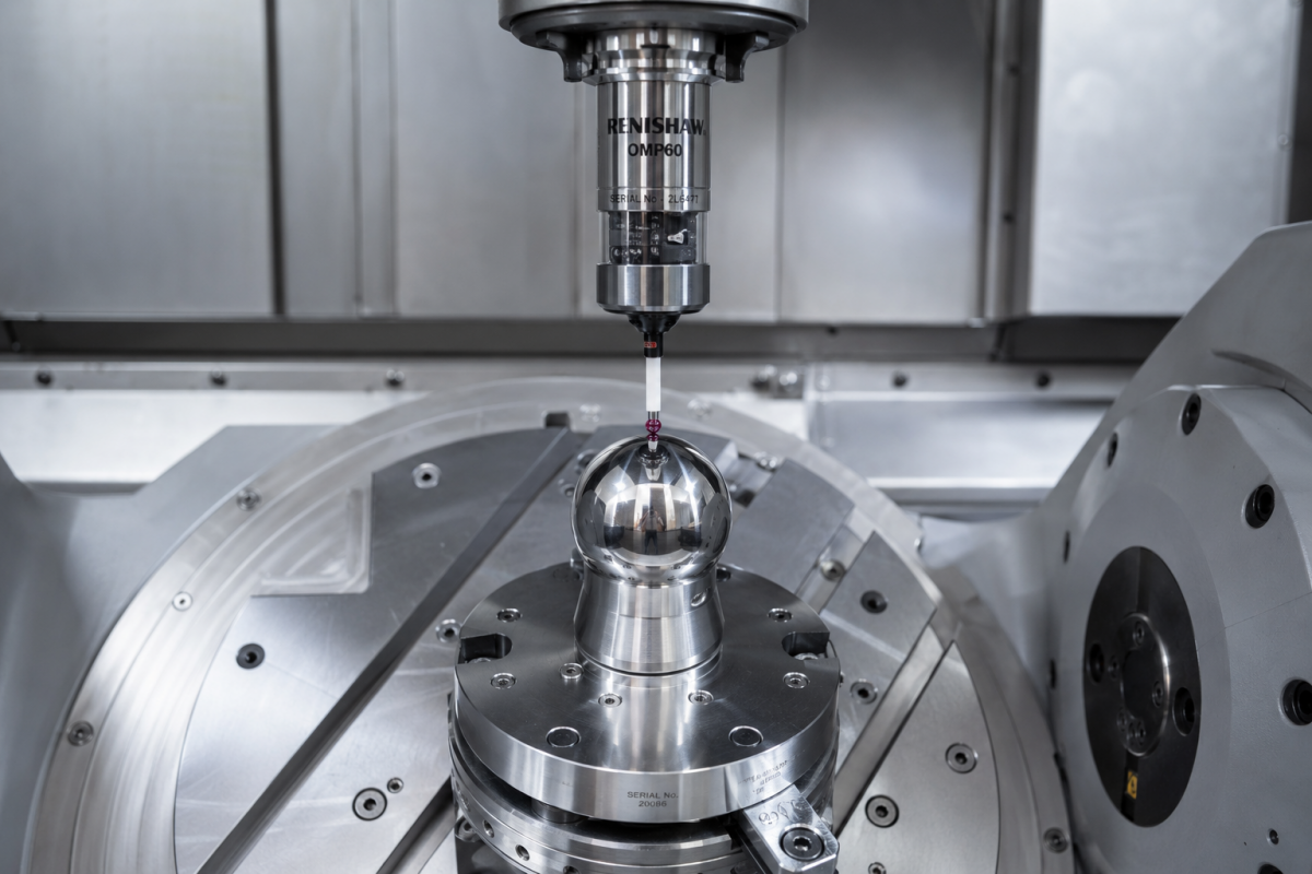
Calibrating rotary axes is the process of measuring and defining the exact Center of Rotation (COR) where the rotational axes intersect relative to the linear machine coordinate system. Thermal shifts, minor structural settling, and mechanical vibrations cause a machine's physical center of rotation to drift slightly over time. If your controller's internal kinematic map thinks the center of the tilting table is even 15 μm away from its actual physical location, your finished parts will suffer from noticeable dimensional errors.To combat this, operators must perform automated center of rotation calibration cycles—commonly referred to as Kinematic Optimization or Rotary Axis Calibration. During this process, a certified calibration sphere is securely mounted onto the machine's rotary table, and an automated touch probe in the spindle automatically measures the sphere at a series of different table angles (such as 0°, 45°, 90° and -45°. The internal CNC controller analyzes these collected data points, isolates the exact spatial pivot coordinates, and automatically updates its internal kinematic parameters to ensure sub-micron alignment accuracy.| Variable / Metric | Initial Rough Alignment | Post-Probing Kinematic Optimization |
|---|---|---|
| Center of Rotation Accuracy | ± 0.050 mm to ± 0.100 mm | ± 0.002 mm to ± 0.005 mm |
| Volumetric Part Accuracy | Loose tolerances only; visible blending marks. | Ultra-tight, aerospace-grade geometric tolerances. |
| Calibration Frequency | Done only during initial machine installation. | Executed weekly or after significant factory temperature shifts. |
Step 3: Program Loading and Multi-Axis Collision Simulation
Program loading and multi-axis collision simulation is the digital validation process where the operator imports post-processed G-code into the machine controller and runs a complete software simulation to catch any structural toolpath interferences. Once your physical workholding is locked down and your kinematics are fully optimized, you can load your production program. In multi-axis manufacturing, you should never trust a program blindly without running it through a localized, high-fidelity controller simulation.At Zhihui Precision, our 5-axis manufacturing professionals—backed by production expertise dating back to 2007—utilize an advanced digital MES system to fully verify and validate G-code toolpaths before execution:Digital Twin Verification: The controller renders an on-screen 3D representation of your specific machine model, your exact tool offset lengths, and your raw stock boundaries.
G-Code Block Analysis: The simulation engine processes the text code word-by-word. It checks for sudden axis movements, invalid feed rates, or instances where a tool holder might get dangerously close to a fixture component.
Clearance Warnings: If any component gets within a predefined safety margin (e.g., less than 1.5 mm from a metal clamp), the simulation halts and flags the exact line of code causing the issue.
Step 4: Executing the Dry Run and First Article Inspection (FAI)
Executing a dry run and First Article Inspection is the final operational verification step where you run the program without cutting material to confirm motion paths, followed by machining and measuring an initial sample part. Before allowing the cutting tool to bite into expensive raw materials, you must perform a physical Dry Run. This bridges the gap between digital software simulation and live production.Step-by-Step Dry Run Protocol
Remove the raw stock material from your vise, or retract your Z-axis work coordinate offset upwards by a safe distance (e.g., +100 mm).
Turn your machine's Feedrate Override dial down to 0%.
Switch the controller over to Single Block mode, forcing the program to execute only one line of code at a time per press of the Cycle Start button.
Press Cycle Start, slowly turn up the feedrate dial, and watch the physical machine move through its motions. Verify that the spindle tilts and swivels smoothly without any unexpected jerks or close calls.
First Article Inspection (FAI)
Once the dry run passes inspection, reset your offsets, remount your stock, and run the program at full speed with coolant engaged. After the machining cycle finishes, do not unclamp the part immediately. Use the machine’s internal touch probe or remove the component carefully to verify critical dimensions on a Coordinate Measuring Machine (CMM).Engineering groups like the National Institute of Standards and Technology (NIST) offer excellent reference documentation for advanced metrology workflows and volumetric validation practices.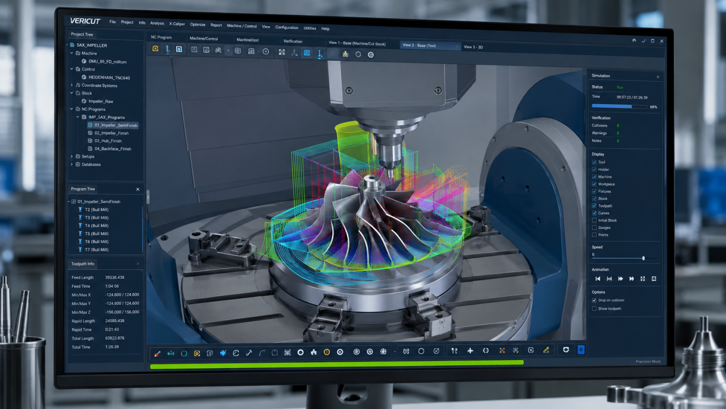
Common Setup Errors and How to Avoid Them
Common setup errors represent the operational oversights, such as incorrect tool length data or outdated kinematic offsets, that degrade part accuracy and cause tool breakage during multi-axis operations. Even experienced operators can occasionally run into issues when handling complex multi-axis workflows. Recognizing these common pitfalls early is key to maintaining a safe, efficient production floor.1. Using Incorrect Tool Gauge Lengths
If an operator inputs a tool length offset that is off by just 0.1 mm, the controller will calculate flawed compensation arcs when the spindle head tilts. This results in unintended steps or gouges on your finished surfaces. Always use automated tool setters to measure your tools under dynamic, rotating conditions.2. Over-Tightening Workholding Jaws
Applying excessive force to self-centering vises can introduce subtle elastic deformations into your raw stock. Once the part is machined and unclamped, the material springs back into its natural state, causing flat surfaces to warp out of spec. Always use a calibrated digital torque wrench to ensure even clamping pressure.3. Neglecting Thermal Stabilization
5-axis machines feature complex castings and high-speed rotary motors that generate considerable heat during extended runs. If you set up a high-precision job immediately after starting a cold machine, thermal expansion will cause your tolerances to drift. Always run a standard 15-to-20 minute spindle and axis warm-up routine to stabilize system temperatures before setting up your work coordinate system.| Common Setup Error | Physical Root Cause | Preventive Operator Action |
|---|---|---|
| Surface Step Marks / Blending Seams | Outdated center of rotation (COR) kinematic parameters. | Run an automated kinematic probing optimization cycle using a calibration sphere. |
| Part Distortion Post-Unclamping | Excessive, uneven clamping torque applied to the vise jaws. | Use a calibrated digital torque wrench to clamp raw stock to exact engineering specifications. |
| Accelerated Tool Wear / Chatter | Excessive tool runout caused by debris inside the spindle taper. | Clean the spindle taper and tool holders using a dedicated taper wiper before mounting. |
Conclusion
Mastering how to set up a 5 axis CNC machine is the defining factor that transforms standard workflows into high-tier precision manufacturing. By strictly adhering to a standardized process—from elevated workholding to precise center of rotation calibration—operators eliminate costly dimensional drift and prevent catastrophic machine collisions. In a multi-axis environment, sub-micron accuracy is the direct result of combining rigorous protocols with advanced production machinery.As component geometries across the medical, robotics, and automotive sectors become increasingly complex, partnering with a digital precision machining services provider simplifies your supply chain. At Zhihui Precision, we leverage over 50 advanced multi-axis centers within our 10,000-square-meter facility to deliver elite 5 axis CNC machining services built to thrive in demanding environments. We provide the reliable sourcing foundation required to execute your complex components with absolute confidence, from initial prototyping to large-scale production.Explore our professional processing capabilities to upgrade your project's performance:Explore Advanced Machinery: Discover our complete setup of over 50 advanced multi-axis production lines and digital manufacturing capacities on our 5 Axis CNC Machining Services page.
Review Production Solutions: See how our high-precision machining workflows tackle complex geometries across automotive, medical, and robotics sectors on our Custom CNC Parts for Different Industries showcase.
Consult with Application Engineers: Ready to eliminate manufacturing bottlenecks and fast-track your delivery? Contact our engineering team through our Technical Consultation & Support page for for expert design for manufacturability evaluation, precise quotes, and tailored custom manufacturing layouts.
Frequently Asked Questions (FAQ)
What is the most common cause of machine crashes during a 5-axis setup?
The most common cause of crashes is failing to update or verify the machine's Center of Rotation (COR) parameters, combined with relying on unchecked tool length offsets. If the controller is using incorrect physical pivot distances, it will calculate flawed compensation moves, which can drive the spindle housing directly into your fixtures or worktable.How often should I calibrate the Center of Rotation (COR) on a 5-axis CNC machine?
As a best practice, you should optimize your machine's kinematics at least once a week. Additionally, you should run a calibration cycle after any severe factory temperature fluctuations (greater than 5°C), after a mechanical collision, or right before running a job with ultra-tight geometric tolerances.Can I use a standard edge finder to set up my work coordinate system (WCS) on a 5-axis machine?
While you can technically use a mechanical edge finder for basic part positioning, it is highly discouraged for precision 5-axis work. Standard edge finders cannot match the speed or sub-micron accuracy of automated spindle touch probes, which are essential for precisely calculating spatial orientations across multiple faces.What is the difference between TCP and WCS in multi-axis machining setups?
The WCS (Work Coordinate System, like G54) defines a fixed origin point on your raw stock material. TCP (Tool Center Point control) is a dynamic real-time tracking mode built into the CNC controller. When TCP is active, the controller tracks the physical tip of your cutting tool and automatically adjusts the linear axes to maintain its precise position relative to the WCS whenever the rotary axes tilt or rotate.Why do I need an elevated self-centering vise for 5-axis milling?
Elevated self-centering vises raise your workpiece high above the rotary table surface. This added height creates a clear clearance envelope, allowing the machine spindle housing to tilt to steep angles without colliding with the machine table, bed, or surrounding enclosures.How does a machine warm-up cycle affect setup accuracy?
High-speed spindles and rotary table motors generate structural heat that causes machine castings to expand slightly. Running a 15-to-20 minute axis and spindle warm-up routine ensures that your machine achieves thermal equilibrium before you measure your datums, preventing dimensional drift caused by thermal expansion.