English
In modern precision manufacturing, achieving complex geometries with micron-level accuracy requires a deep understanding of advanced machining systems. Whether you are developing aerospace components, medical implants, or intricate automotive dies, knowing the exact mechanics behind your production method prevents costly design errors and optimizes manufacturing workflows.
At Zhihui Precision, our high-precision multi-axis machining services transform complex designs into high-tolerance components. This guide breaks down the core software and mechanical workflows we leverage daily to guarantee your part quality.
Why Do You Need to Learn About 5 Axis CNC Machine?
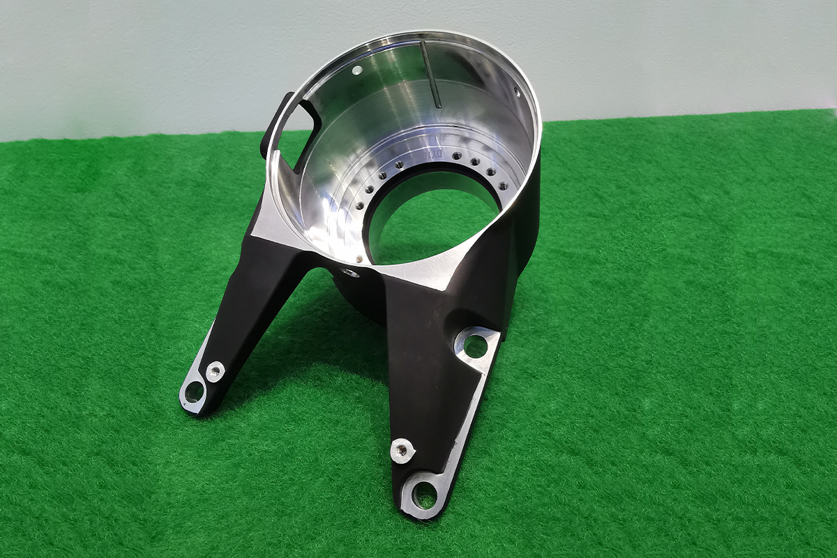
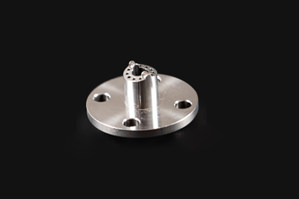
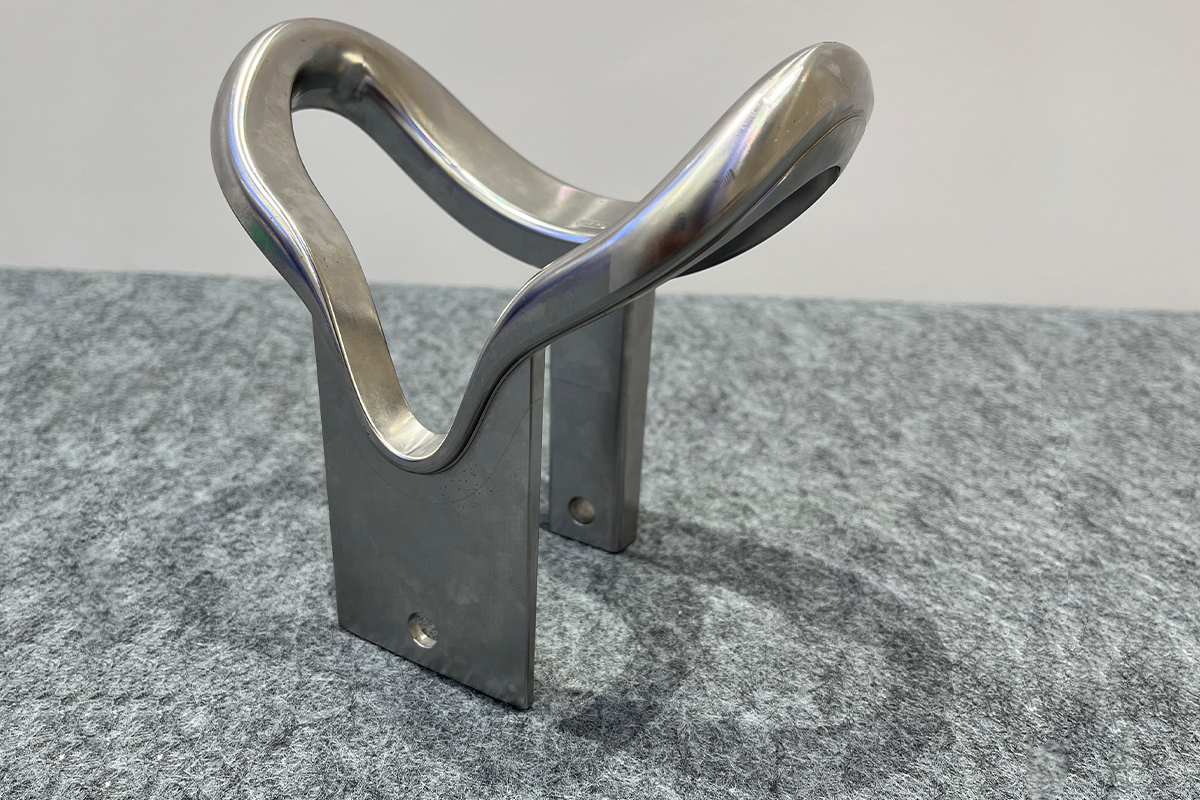
Learning about 5-axis CNC machining is the foundational process of understanding how multi-directional tool movement reduces production setups, enhances surface finishes, and optimizes structural integrity for highly complex components. Understanding how does a 5-axis CNC machine work changes how you approach the design for manufacturability (DFM) phase. Traditional 3-axis machining restricts tool access to three linear axes (X, Y, and Z). When a part features undercut geometries, angled pockets, or compound curves, a 3-axis workflow requires multiple physical setups. Each setup forces an operator to manually re-fixture the part, introducing tolerance stack-ups (often varying by ±0.05 mm or more) and increasing labor overhead.
By implementing a 5-axis manufacturing approach, engineers gain access to a multitude of operational advantages:
Single-Setup Efficiency (Done-in-One): Complex geometries that used to require 4 to 6 separate setups can now be completed in a single operation. This dramatically cuts lead times and eliminates fixture-to-fixture positioning errors.
Optimal Tool Vectoring: The machine dynamically adjusts the relative angle between the cutting tool and the raw material. This allows the system to utilize shorter, high-rigidity end mills, which reduces tool deflection, suppresses chatter, and yields a superior surface finish (Ra < 0.4 μm).
Geometric Freedom: Features like deep pockets, tight draft angles, and organic contours become standard deliverables rather than high-risk manufacturing bottlenecks.
How Does a 5-Axis CNC Machine Work? The Complete Working Principle
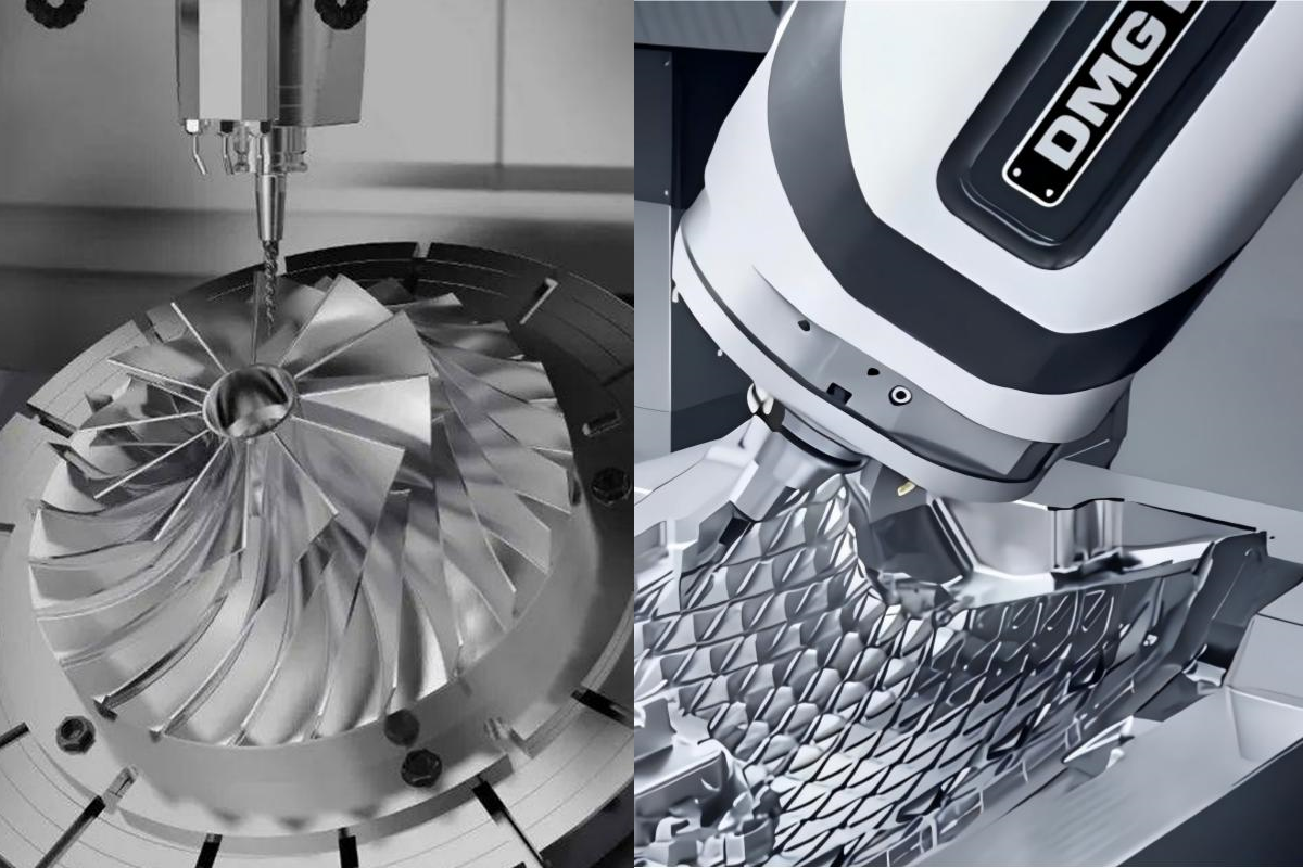
The fundamental working principle of a 5-axis CNC machine relies on the synchronized execution of three linear axes (X, Y, Z) and two rotational axes (A, B, or C) to maneuver a cutting tool seamlessly around a workpiece from any direction. To grasp how this works, we must analyze the spatial degrees of freedom. A standard machine moves linearly along three planes: the X-axis (left to right), the Y-axis (front to back), and the Z-axis (up and down). A 5-axis machine introduces two rotational axes selected from A (rotation around X), B (rotation around Y), and C (rotation around Z).
The precise combination of these rotational axes defines the physical architecture of the machinery. Modern CNC centers generally fall into three kinematic layouts:
Trunnion (Table/Table) Configuration
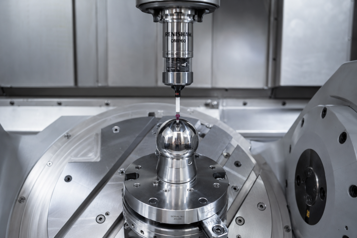
In a trunnion-style machine, both rotational axes are built into the work table. The table tilts (typically along the A or B axis) and rotates (along the C axis) while the spindle remains vertically or horizontally fixed. This setup provides excellent torque and heavy material removal capabilities, making it ideal for heavy metals and compact, complex components.
Swivel Head (Head/Head) Configuration
Here, the work table remains flat on the machine bed while all rotational capabilities are engineered into the spindle head. The head tilts and swivels along two rotational configurations. Because the heavy workpiece does not move, this configuration is the industry standard for large, oversized components used in aerospace structural frames and heavy transport industries.
Head/Table (Hybrid) Configuration
This layout splits the rotational responsibilities. The spindle head handles one tilt axis, while the rotary table executes the other. This hybrid structure offers a balanced, versatile environment capable of handling medium-to-large parts with highly dynamic tool paths.
Kinematics of 5-Axis Machining: Tool Path Generation and Machine Coordination
Kinematics in 5-axis machining is the mathematical framework that maps a component's structural CAD/CAM coordinates into real-time linear and rotational physical movements across a unified machine coordinate system. Executing a flawless multi-axis cut requires continuous coordinate transformation. When a machine moves simultaneously across 5 axes, the tip of the tool must maintain exact contact with the material while the body of the tool and the machine components tilt dynamically. To achieve this without manual geometric offsets, modern CNC controllers rely on a crucial feature called RTCP (Real-time Tool Center Point control) or TCPM (Tool Center Point Management).
Without RTCP, if a rotary axis tilts by 10°, the linear axes (X, Y, Z) must compute massive compensation moves to keep the tool tip in place, because the pivot point is fixed at the machine center. RTCP shifts the controller’s reference point directly to the tip of the cutting tool. The internal CNC controller dynamically tracks the tool tip length and orientation vector, automatically modifying the X/Y/Z commands in real time at a rate of thousands of blocks per second.
| Feature / Capability | 3+2 Axis Machining (Positional) | Continuous Simultaneous 5-Axis Machining |
|---|---|---|
| Kinematic Execution | Rotational axes lock into a fixed orientation; cutting is done using only 3 linear axes. | Linear and rotational axes execute movements simultaneously during the cut. |
| Tool Path Vector | Fixed plane angle per cutting cycle. | Continuous, dynamically altering vector coordinates (I, J, K). |
| Ideal Application | Prismatic components with features on multiple flat faces. | Complex organic shapes, impellers, turbine blades, and spiral molds. |
| Surface Finish Quality | Visible witness marks or blending seams between orientation changes. | Smooth, uniform scallop heights and excellent surface continuity. |
The Critical Role of CAM Software in 5-Axis Toolpath Programming
CAM software in 5-axis programming serves as the computational engine that interprets 3D CAD geometry to generate optimized, collision-free cutter locations and tool axis vectors. Human programmers cannot calculate 5-axis toolpaths by hand. Engineers rely on advanced Computer-Aided Manufacturing (CAM) platforms—such as Autodesk Fusion 360, Mastercam, Hypermill, or NX CAM—to plot out the tool’s movement.
When a CAM developer creates a multi-axis path, the software calculates two core metrics: the Cutter Location (CL Data) and the Tool Axis Vector. The tool axis vector is represented by I, J, and K values, which define the directional orientation of the tool relative to the 3D space.
Advanced CAM software provides sophisticated strategies to control how the tool tilts along complex surfaces:
Lead/Lag Angles: The tool tilts forward or backward relative to the direction of travel, ensuring the cutting action occurs on the efficient outer flutes of the end mill rather than the zero-velocity dead center of a ball-nose mill.
Tilt Side Angles: The tool tilts sideways to clear high vertical walls or localized fixturing.
Surface Normal Orientation: The tool maintains a strict perpendicular or predetermined offset angle relative to the underlying 3D CAD surface patch.
For a deeper dive into modern manufacturing standards and digital workflows, resources like the ISO Manufacturing Standards provide excellent frameworks for multi-axis geometric specifications.
Post-Processing: How CAM Output Becomes Machine-Ready G-Code
Post-processing is the dedicated translation step that converts generic neutral CAM toolpath data (CL file) into machine-specific, controller-readable G-code text commands. When CAM software finishes calculating a path, it saves it in a universal format called a Cutter Location file (.cl). This file outlines where the tool needs to go, but it doesn't know what specific machine model, CNC controller, or axis configuration is actually running on your factory floor. This is where the Post-Processor comes in.
The post-processor is a highly customized translation script tailored to a specific machine-controller combination (e.g.,a multi-axis production line running advanced Heidenhain, Siemens 840D, or Fanuc 31i control systems). The post-processor translates neutral spatial coordinates into explicit, hardware-compatible code structures.
Critical Post-Processor Translation Tasks
Kinematic Mapping: Resolving how to translate an abstract I, J, K direction vector into physical tilt angles for an A, B, or C axis based on the machine's exact pivot-to-gauge-line distances.
Axis Travel Limits: Managing situations where a machine axis hits its physical travel limit. If a rotary axis can only tilt to +95° but the toolpath asks for +100°, the post-processor must calculate an alternate, safe orientation to continue the cut without gouging the part.
Syntax Injection: Inserting specific M-codes for coolant control, safety retract routines, and enabling proprietary high-speed surface smoothing algorithms.
Collision Avoidance and Simulation in 5-Axis Operations
Collision avoidance and simulation systems are the digital twin verification tools used to analyze, predict, and eliminate potential physical impacts between machine components, fixtures, tools, and workpieces before running a program. Because 5-axis machines move through complex, non-linear paths, the risk of a physical crash is much higher than in traditional machining. If a rotary axis swings quickly, the tail end of a spindle housing could strike a fixture component. To prevent catastrophic hardware damage, engineers use specialized simulation software like VERICUT or integrated CAM machine simulation modules.
This process builds a high-fidelity Digital Twin—a complete, mathematically accurate 3D model of the machine's physical workspace, fixtures, stock material, and tool holder assemblies.
| Simulation Layer | Key Verifications & Metrics Checked |
|---|---|
| Component Interference | Analyzes spatial clearance between the spindle head housing and the workholding fixtures. |
| Axis Over-Travel | Flags movements that exceed physical limits, preventing unexpected axis stalls. |
| Gouge & Stock Analysis | Compares the simulated machined stock against the original CAD file to find unintended cuts or unmachined stock. |
| G-Code Verification | Directly parses the final post-processed G-code text, catching any translation errors introduced during the CAM export process. |
Summary: The Full 5-Axis CNC Machining Workflow
The 5-axis CNC machining workflow is the end-to-end manufacturing sequence that transforms an initial concept into a finished, physical component through integrated engineering and automated execution phases. To successfully execute a multi-axis project, every step of the digital-to-physical chain must link together seamlessly. The entire workflow follows a highly structured, repeatable sequence:
CAD Modeling & DFM Analysis (Phase 1: Engineering Design) Create the precise 3D component model within CAD software. Perform Design for Manufacturability (DFM) reviews to ensure features can be accessed effectively by standard tool geometries.
CAM Toolpath Generation (Phase 2: Digital Programming) Import the clean CAD data into CAM software. Define raw stock parameters, design rigid fixturing models, select cutting tools, and program simultaneous 5-axis toolpaths using appropriate lead/lag or surface-normal vector controls.
Digital Twin Simulation & Verification (Phase 3: Risk Mitigation) Run the completed toolpaths through comprehensive digital twin simulation modules. Check for spatial interferences, tool gouges, and axis over-travel issues, adjusting parameters until the routine is verified as 100% safe.
Post-Processing Conversion (Phase 4: G-Code Translation) Process the verified toolpaths through a custom post-processor designed for your specific machine setup. This generates a machine-ready file containing precise linear, rotary, and contextual hardware commands.
Machine Setup & Live Execution (Phase 5: Physical Production) Load the finalized G-code file into the CNC controller. Mount the raw stock material on the machine bed, probe the initial reference datums, load calibrated tooling assemblies, and execute the machining cycle under active RTCP control.
Frequently Asked Questions (FAQ)
What is the main difference between 3-axis, 4-axis, and 5-axis CNC machining?
A 3-axis machine operates along three linear axes (X, Y, Z). A 4-axis machine adds a single rotational axis (usually the A or B axis via a rotary indexer). A 5-axis machine introduces two simultaneous rotational axes (A, B, or C), allowing the cutting tool to approach a workpiece from any angle across a continuous path.
What are RTCP and TCPM, and why are they vital for 5-axis work?
RTCP (Real-time Tool Center Point control) and TCPM (Tool Center Point Management) are advanced real-time controller capabilities. They shift the machine's reference point from the center of the mechanical rotation axis directly to the cutting tip of the tool. This enables the controller to automatically compensate the linear axes (X, Y, Z) when rotational axes shift, ensuring precise tool paths without calculating manual geometric offsets.
Is a 5-axis machine always better than a 3-axis machine?
Not necessarily. For simple, flat, or prismatic components, a 3-axis machine is often more cost-effective and faster to program. 5-axis centers excel at complex, organic geometries, deep pockets, contoured surfaces, and parts that would otherwise require multiple manual setups.
What is the difference between 3+2 machining and continuous 5-axis machining?
In 3+2 (positional) machining, the machine uses its two rotational axes to tilt the workpiece or spindle into a fixed orientation. Once locked into place, the cutting action occurs using only the three linear axes. In continuous simultaneous 5-axis machining, all five axes move dynamically at the same time during the cutting process, allowing the tool to follow complex curves and organic geometries.
How do post-processors affect 5-axis machining safety?
A post-processor acts as a translator between generic CAM software files and the specific CNC controller on your factory floor. If a post-processor is incorrectly configured for a machine's unique kinematics, axis travel limits, or pivot distances, it can output faulty G-code commands, leading to inaccurate part dimensions or severe machine collisions.
Which industries rely most heavily on 5-axis CNC machining capabilities?
Industries that require highly complex, lightweight, or safety-critical components depend on 5-axis machining. This includes the aerospace industry (for turbine blades, impellers, and structural bulkheads), the medical field (for custom orthopedic implants and complex instruments), and the automotive/mold-making sectors (for complex stamping dies and high-tolerance injection molds).
Partner with Zhihui Precision for Next-Generation Manufacturing
Executing complex projects requires robust machining capabilities, precise execution, and proven manufacturing expertise. At Zhihui Precision, we deliver high-performance 5-axis machining services engineered to handle demanding tolerances and complex geometries.
Explore our professional processing capabilities to align your next project with world-class multi-axis performance:
Explore Advanced Machinery: Browse our complete lineup of multi-axis machining services centers on our 5 Axis CNC Machining page.
See Industrial Solutions: Learn how we solve complex manufacturing challenges across various industries on our dedicated 5-Axis CNC Machining Application platform.
Get Expert Engineering Support: Ready to evaluate your next complex project? Reach out to our application team via our Contact Us page for expert guidance on Design for Manufacturability (DFM) analysis, precise lead-time estimation, and instant sourcing quotes.