English
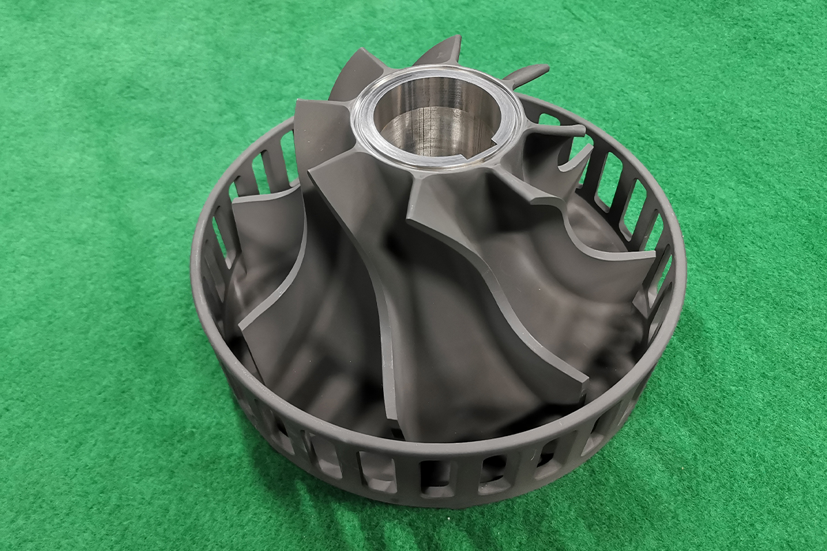
Impellers combine thin blades, narrow channels, changing curvature and critical hub/bore relationships. The machining plan must balance tool access, deflection, surface integrity, cycle time and residual imbalance.
Five-axis motion improves access, but it also introduces collision, rotary-axis and tool-vector decisions. A smooth simulation is not proof of an acceptable physical part.
Start with Stock and Datum Strategy
Material form, heat treatment and grain requirements influence stock allowance and distortion. Establish the bore/hub and axial reference used for machining and later balancing. Protect enough datum material until the final operations are stable.
For 5-axis impeller machining, provide the full design model plus a drawing that controls blade profile, thickness, leading/trailing edges, hub, bore and runout.
Rough Without Destabilizing the Blades
Use toolpaths that maintain a stable stock distribution around blades.
Remove material progressively from passages rather than finishing one thin blade beside heavy stock.
Control cutter engagement and chip evacuation in deep channels.
Monitor tool condition where recutting can damage thin edges.
Leave enough stock for semi-finishing to remove roughing effects.
Recheck datum/runout after high-removal stages.
Select Tool Axis and Contact Point
Tilting a ball or barrel tool can avoid zero cutting speed at the tip and improve effective contact, but machine limits, holder clearance and blade flexibility constrain the angle. Lead/lag and side tilt should change smoothly to avoid witness marks.
Use collision checking that includes spindle, holder, tool, fixture and remaining stock. Validate postprocessed machine motion, not only CAM geometry.
Control Surface and Edge Integrity
| Area | Risk | Control |
|---|---|---|
| Blade surface | Scallops, chatter and tool-vector marks | Stepover, stiffness, smoothing and tool condition |
| Leading edge | Thickness loss or burr | Protected stock and controlled finishing |
| Fillet | Tool interference or stress raiser | Appropriate cutter/profile verification |
| Passage | Residual stock and inaccessible burr | In-process probing/visual access plan |
| Bore/hub | Runout affecting assembly/balance | Dedicated finishing and inspection datum |
If hand polishing is allowed, specify regions and material-removal limits. Uncontrolled polishing can change blade profile and mass distribution.
Inspect Geometry and Balance in Sequence
Use CMM or optical scanning to compare blade profiles, thickness and spacing with the model. Establish how hidden surfaces and thin edges will be measured and how point-cloud alignment relates to drawing datums.
Static or dynamic balancing requirements depend on speed and rotor assembly. Define whether the machined impeller alone is balanced, which correction zones are allowed and whether final balance occurs after coating or assembly. Record mass-removal locations for process feedback.
Frequently Asked Questions
Why are impellers machined on five-axis equipment?
Rotary motion improves tool access to curved blades and narrow passages and can keep related geometry in fewer setups.
Can surface finish be guaranteed everywhere?
Only when regions, measurement method, accessibility and post-processing are defined. Hidden passages may need special verification.
Is balancing part of CNC machining?
It can be included or performed downstream. The RFQ must define component/assembly state, speed class, correction zones and report.
What model quality is required?
Provide clean production-intent surfaces/solids and a drawing that controls datums, profiles, edges, finishes and inspection.
Connect Toolpath, Inspection and Balance
Zhihui Precision can review impeller stock, geometry, material and verification requirements. A robust plan treats blade machining, deburring, metrology and balance as one controlled sequence.